Physical Address
304 North Cardinal St.
Dorchester Center, MA 02124
Physical Address
304 North Cardinal St.
Dorchester Center, MA 02124


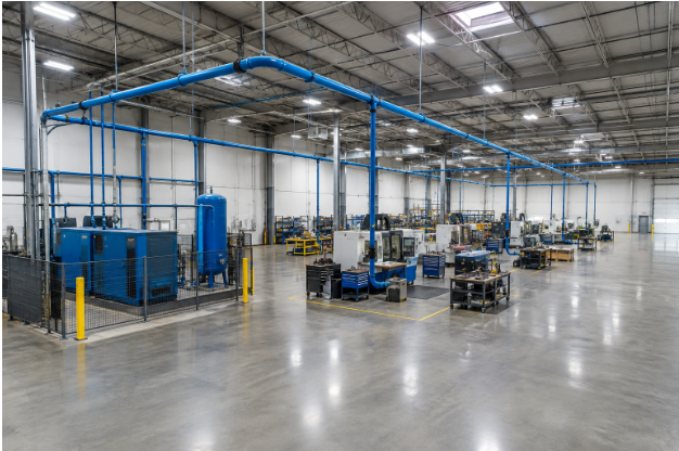
A compressed air system is more than a compressor and a few pipes. The distribution layout affects whether machines receive stable pressure, whether operators can work without frequent interruptions, and how easily the system can be expanded. Selecting compatible compressed air fittings, piping, valves, and point-of-use components is part of building a reliable network from the compressor room to the farthest workstation.
A good layout starts with actual operating needs rather than a pipe size that worked in another building. When demand, routing, drainage, maintenance access, and future production changes are considered together, a facility can avoid costly rework and reduce the temptation to compensate for distribution problems by increasing compressor pressure.
Pipe routing and component selection influence pressure stability, air velocity, moisture handling, and serviceability. Long runs, undersized branches, restrictive fittings, and dead-end sections can make it harder to deliver air where it is needed. The U.S. Department of Energy identifies leak reduction, pressure management, maintenance, storage, and controls among the practical ways to improve compressed air system performance.
Begin by listing every air-powered tool, machine, cylinder, valve, nozzle, and process. Record each item’s required pressure, expected airflow, duty cycle, and hours of operation. Separate steady demand from short, high-flow events, then consider shift changes, seasonal work, and planned equipment purchases. This demand profile provides the design team with a more useful starting point than simply matching the current compressor outlet size.
Pipe diameter affects air velocity and friction loss. A line that is physically large enough to connect to a machine may still be too small to supply it consistently during peak use. Size mains and branches using peak airflow, developed length, operating pressure, fittings, allowable pressure drop, and expected future capacity. Confirm the final design with a qualified engineer or a recognized sizing method, especially when the system serves critical production equipment.
Map the compressor room, production zones, work cells, and likely expansion areas before installation begins. Position the main header to serve multiple areas without excessive branch lengths, and use branch isolation valves where sections may need independent service.
Keep drops accessible and protect them from forklifts, impact, heat, and other avoidable hazards.
Every elbow, reducer, valve, filter, hose, and quick connection adds resistance to flow. Use smooth routing where practical, avoid unnecessary turns, and review long hoses and narrow point-of-use hardware as part of the system rather than as minor accessories. Measure pressure at the compressor, main header, and remote points under normal demand conditions. Raising compressor discharge pressure can mask a distribution issue, but correcting the restriction is usually the more direct solution.
Leak prevention should begin during design. Limit unnecessary joints, use joining methods suitable for the pipe material and pressure rating, and support lines to prevent vibration from straining connections. Clearly label isolation valves and service areas. After commissioning, establish a routine for visual checks and ultrasonic leak surveys where appropriate.
A small leak near a noisy work cell can be easy to miss while it runs through every production shift. Tagging the location, recording the repair date, and confirming the repair during a follow-up inspection helps prevent a temporary defect from becoming a permanent operating cost.
As compressed air travels through cooler piping, its temperature can fall, and moisture may condense. Plan for this with appropriate receivers, dryers, filters, pipe slope, drain points, and drop-leg arrangements. Service drops should be arranged so that the collected liquid does not flow directly toward tools or sensitive equipment. Moisture control is particularly important for finishing operations, pneumatic controls, electronics, food-related processes, and other applications with defined air-quality requirements.
Future capacity is easier to include while ceilings are open and production areas are accessible. Reserve space for additional branches, install isolation valves at logical zones, document spare connection points, and avoid locating the main header where later work would require a major shutdown. For example, a plant that adds a production cell every few years can benefit from planned tie-in points rather than repeatedly cutting into an active main line.
Place valves, regulators, filters, drains, and gauges where personnel can safely reach them. Use clear labels and keep piping diagrams up to date after every expansion, relocation, or major repair. Provide enough working room around service points, inspect supports and flexible connections, and use isolation points that allow one zone to be serviced without unnecessarily shutting down the entire facility.
Facilities can also use the U.S. Department of Energy’s compressed air improvement resources to support assessments of leaks, controls, maintenance, and energy use.
A loop can be useful when demand is spread across a large area or changes between production zones. A simple branch layout may be adequate for a small facility with short runs and predictable loads.
The allowable amount depends on the equipment, distance, flow pattern, and required pressure at the point of use. Set a design target before finalizing pipe sizes and fittings.
Expansion may be practical when the existing system has available capacity, accessible isolation points, suitable pipe sizing, and accurate records. Review pressure and airflow before adding new demand.
Use routine visual inspections, periodic leak surveys, and follow-up checks after repairs or system changes. The appropriate frequency depends on operating hours, system size, and the consequences of a pressure loss.
A reliable compressed air network is built around real demand, suitable pipe sizing, efficient routing, moisture control, leak prevention, and maintainable access. The best layout is not always the shortest route. It is the one that delivers stable air today while leaving practical options for the facility’s next change.